Horn Assembly. Am I missing something?
by Nissan-man from down-under
OK boys and girls, at great expense to the management, I have taken the device apart and photographed all the pits and pieces. First up, let me say that the designer could have made it more complicated but he must have run out of time
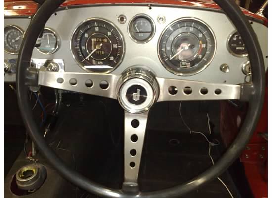
In the beginning there was a wheel. The horn button has a small notch at the junction of the button and the body right at the base of the button. Insert a small flat bladed screwdriver into the notch and lever gently to remove the button.
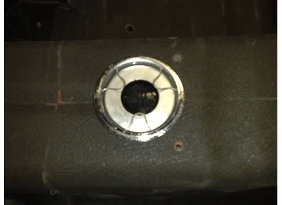
The underside of the button shows the wave spring that holds the "d" emblem in place as well as holding the decorative button to the body.
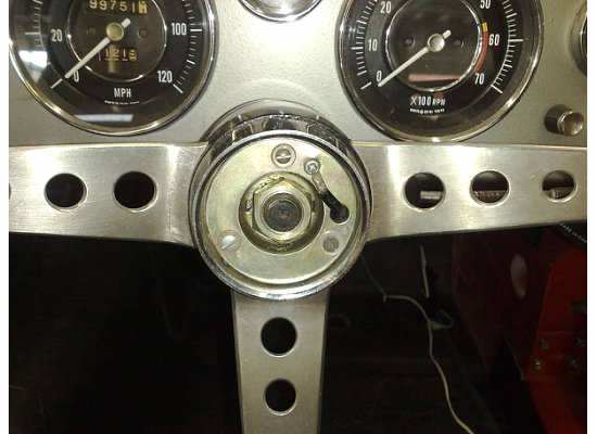
The steering wheel now shows the horn HOT wire and the screw terminal to which it attaches. The HOT plate is LIVE with 12V from the Horn Relay.
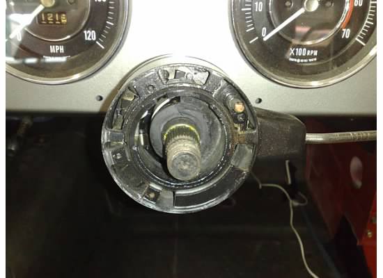
With the steering wheel removed, you can see the contact button at 2 o'clock. This is the 12V feed and the button rubs on the contact ring bonded to the backside of the steering wheel hub......
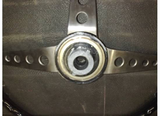
......which is shown here.
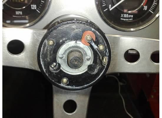
The HOT wire appears as a screw terminal on the steering wheel hub and is insulated from the metal parts. The little pig tail goes through the button body......
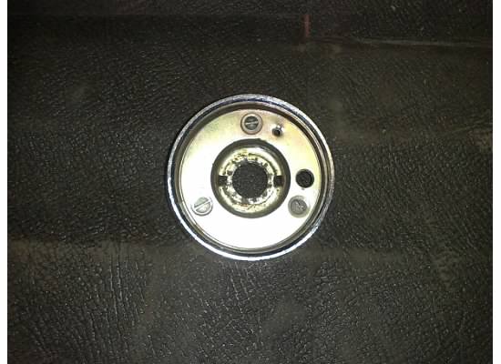
......and is screwed down on this plate at 1 o'clock.
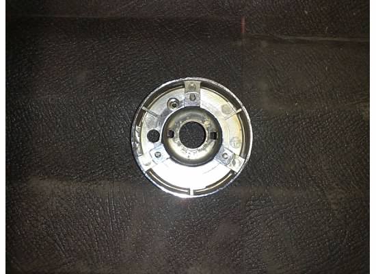
The backside of the horn body shows the two locating tabs at 3 and 9 o'clock which lock into the steering wheel hub.
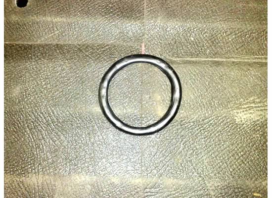
This what the parts book describes as the Horn Spring. It is a round piece of rubber section designed to separate the GROUND and HOT parts of the horn metal work.
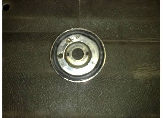
The horn spring in the correct position.
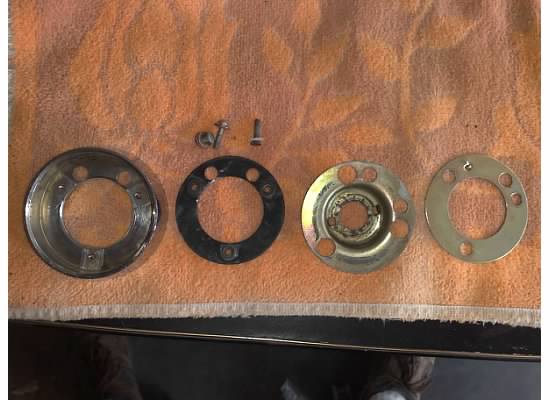
Now here is where all the complication arises. These are the component parts of the horn button. From the left we have the chrome horn button, insulating disc, grounding ring and HOT ring.
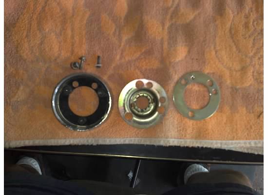
The insulating disc is inserted into the horn ring.....
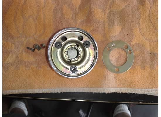
......the grounding ring is located over the insulating disc where the little bosses are.......
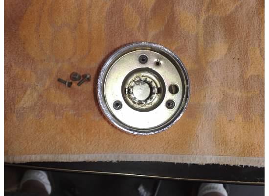
......the HOT ring is placed over the insulating ring bosses and held down with three metal thread screws with insulating washers. That means that once the 12V pig tail is screwed to the HOT plate, the horn relay can be energized by forcing the HOT plate onto the grounded plate.The contact to ground out the relay wire is done between the grounding plate which is grounded when the steering wheel retaining nut in tightened, and the HOT plate under the spring tension of the rubber ring.
Now, that wasn't so hard, was it :*>)
Here is the line drawing from the Parts Manual: -
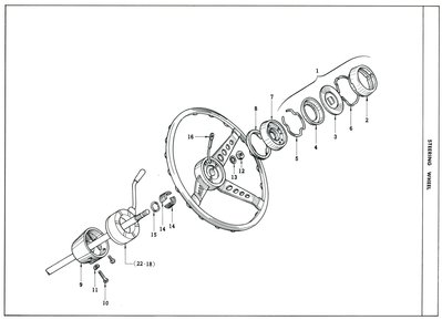
It seems to avoid all the important parts that make up the actual horn contacts. Ah well! Such is Life!
- Nissanman, just trying to help.
- 1965 SP310 Engine No. G-93326 Car No. SP310-10817
- http://nissanman.shutterfly.com/117
- She's on the road again!
